Building a NadaNet Adapter
Michael J. Mahon – December 5, 2004
Revised - July 21, 2005
Introduction
A number of people have requested a detailed "how-to" article about constructing a NadaNet adapter, so here it is.
The schematic diagram is shown in NadaNet: A Native Network for the Apple II, but it need not be referenced to build the adapter.
Note that the components are readily available at electronics parts stores, like Radio Shack, or can be ordered from electronic distributors.
Soldering is required, and should be done with a small, 30-watt or less, thin-tipped soldering iron. The solder used should be 60/40, rosin core solder of small gauge (28 gauge is fine) so that the amount of solder can be easily controlled.
If you are not experienced at soldering small electronic components in close quarters, refer to articles on the web or seek advice from someone with experience. Practice is essential to good technique. Recovering from a soldering error may be much more difficult than avoiding it in the first place. Although most components are quite heat-resistant, the plastic of sockets and the plastic insulation on wires is much less tolerant of sustained heating. All your solder connections should be made quickly and with sparing amounts of solder, but with good solder flow. Developing good soldering skills will be an asset to you in many endeavors.
All construction is done on a 16-pin machined-pin DIP socket, and so some dexterity and small needlenose pliers are required.
The Components
There are few components in a NadaNet adapter. They are:
2 – 2N4401 NPN transistors (or other medium-gain NPN transistor)
1 – 1N914 silicon diode (or other signal switching diode)
2 – 4.7k Ohm, 1/8 watt resistors
1 – 0.1uF, 50v axial lead capacitor
1 – Machined-pin 16-pin DIP socket
A couple of inches of insulated solid wire of #28-#30 gauge.
About 6-12 inches of 2-conductor cable
The cable can be the type of cable used for phone wiring, with only two of its four conductors used. I used some 3-conductor "intercom cable" and used only two of its stranded copper conductors. This cable is used to connect from the adapter to an RCA network connector on the back of your computer. Shielding is irrelevant for this cable.
Construction
As with all construction projects, begin by clearing a space on a smooth surface where you can work with good light. Arrange the components and your tools for easy access.
In the steps that follow, both a pictorial drawing of the assembly step and a photo of the completed step will be shown side by side. They will serve as a visual guide to the description of the step. As you form the leads and make the connections described below, be careful not to connect accidentally to any unintended pins or wires.
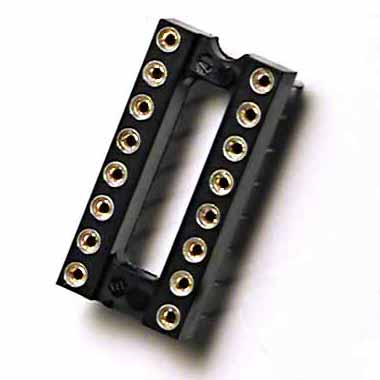
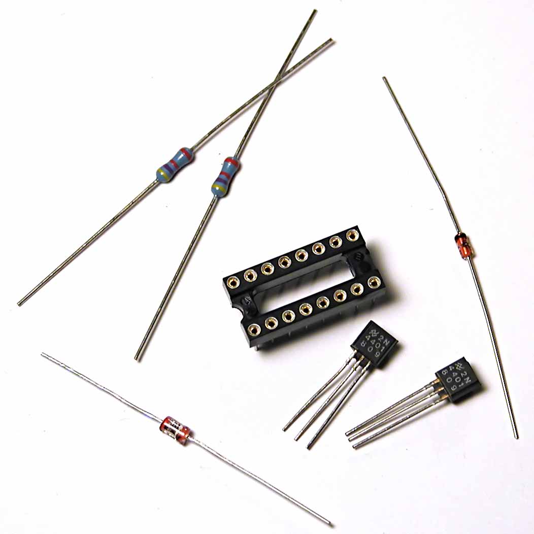
Here is a picture of the components, minus the wire.
Step 1
Take the 16-pin DIP socket and place it in front of you, oriented with the pins facing down and the "notch" at the top.
|
|
|
Step 2
Add the 0.1uF decoupling capacitor between the "Gnd" and "+5v" sockets. Hold the capacitor up to the socket to measure where to bend the leads. Bend both leads 90 degrees in the same direction with the needlenose pliers and trim them to about 1/8" after the bend. Then use the needlenose pliers to insert the bent ends into the sockets as far as they will go.
|
|
|
Step 3
Add one of the 4.7k resistors between "Gnd" and "PB1" by measuring, bending, and trimming the leads as you did with the capacitor, but this time, trim the "Gnd" lead after the bend to about 1/16". Using the needlenose pliers, insert the "PB1" end into the socket as far as it will go, and gently position the resistor so that the slight springiness of the "PB1" lead holds the short bent part of the other lead against the "Gnd" socket well. (We will use this "spring" method of positioning several components until it is time to solder them.)
|
|
|
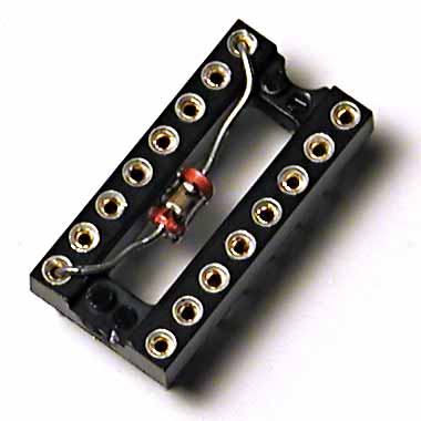
Step 4
Install the 1N914 diode between the "+5v" and upper "n.c." sockets, orienting it so that the cathode, marked by a black stripe, is connected to "+5v". In this case, the "n.c." bent lead should be about 1/8" and the "+5v" lead should be trimmed to about 1/16". The "n.c." lead is fully inserted in the socket, and the other lead is positioned in the "+5v" socket well using the springiness of the other lead. (I’m sure you get the picture of how this works, now.)
|
|
|
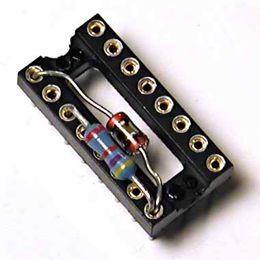
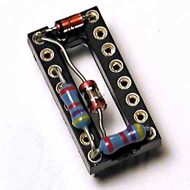
Step 5
Add the second 4.7k resistor between the "Gnd" and lower "n.c." sockets. As you would expect, the "n.c." side of the lead will have a 1/8" bent part, and the "Gnd" side will be 1/16". Fully insert the "n.c." side and position the other lead in the well of the "Gnd" socket. You can now solder the "Gnd" socket.
|
|
|
Step 6
To install the first 2N4401 transistor, cut some plastic insulation removed from small wire and place it over the leads of the transistor. Then orient it so that the flat face of the package faces down and form the leads as shown in the picture. If you have chosen the insulation lengths appropriately, it will cover the leads as shown. Slide the collector (C) and emitter (E) leads under the leads of the diode and form the base (B) lead so that it can be inserted into the "AN1" socket in the usual way. The "+5v" socket can now be "tack" soldered (another lead will be added).
|
|
|
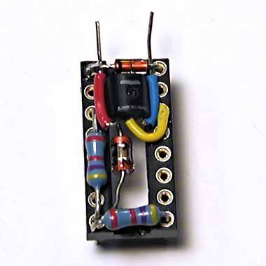
Step 7
Now prepare the second 2N4401 transistor, also with its flat side down, with insulation on its leads. Note that the collector (C) lead on this transistor needs to be somewhat longer than the others. The leads of this transistor are "crimped" to the other component leads by forming small "hooks" with the needlenose pliers. Now the "+5v", the "PB1", and the "AN1" sockets can be soldered and excess leads trimmed.
|
|
|
Step 8
Now a short piece of insulated solid wire is added between the two "n.c." sockets. The stripped ends of the wire are crimped to the existing component leads before soldering both "n.c." sockets. Be careful to avoid creating a short to any other socket pins, since the wire does not stand up off the socket, there is little "height" clearance near the ends.
|
|
|
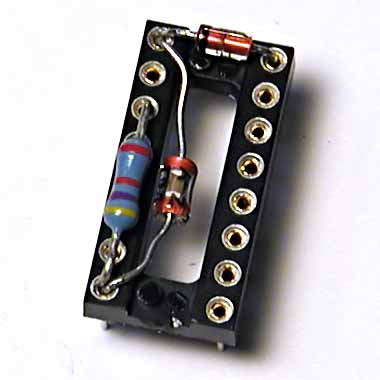
Step 9
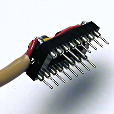
Finally, a piece of 2-conductor cable is connected to the "Gnd" and lower "n.c." sockets by "tack" soldering to the existing connections. The cable should be approximately 6" long unless you are using it in an Apple IIgs, in which case it should be about 12".
|
|
|
Step 10
If you are planning to use the adapter in an Apple IIgs, then you may want to break off one pin, since that pin, while not connected (n.c.) on all other Apples, is used for a fourth switch input on the Apple IIgs. The pin to break off is the "lower n.c." pin, pin 9, as shown in the picture below. You need not remove it if you don’t use the other switch.
Final Assembly
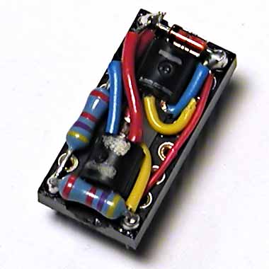
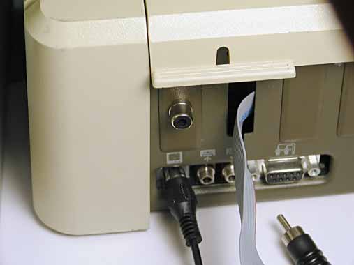
The adapter is essentially complete, but an RCA connector needs to be installed in the back panel of the Apple II and the cable soldered to it, as shown below. Note that the "Gnd" wire goes to the shield and the network bus (connected to pin 9 of the socket) goes to the center pin connector.
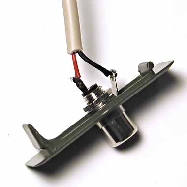
The RCA connector has been installed in a 1/4" hole drilled in one of the cover plates in the back panel of the Apple //e. The panel is thin enough, and the cutouts just wide enough, that the completed adapter can be "wiggled" carefully through the back panel, allowing the cable to be soldered prior to installation. This is not the case with the Apple IIgs, whose back panel is too thick to permit the adapter to pass. Installing an adapter in the Apple IIgs is easiest if the cable is threaded from the inside of the case and soldered outside before the cover plate is reinstalled. In both cases, the installation is quite professional in its appearance.
|
|
|
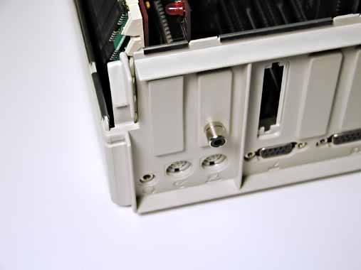
Because of the cover attachment method on the Apple IIgs, it is necessary to locate the RCA jack carefully, so that it will clear both the back panel cutout and the attachment clip.
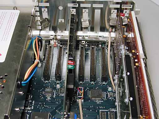
Cable routing is straightforward for 8-bit Apples, but the Apple IIgs is different. The location and orientation of the 16-pin game port socket in the Apple IIgs is unique. In the Apple IIgs, the adapter’s cable emerges facing the front of the machine, not the back, and is near the middle of the main board. The picture below shows an out-of-the-way routing for the longer cable in an Apple IIgs.
Connecting Machines
NadaNet connections are made with good quality male-male RCA cables. If the total interconnecting cable does not exceed 8 feet per machine (adapter), no additional "pulldown" should be required. The adapter should have no problem driving up to 250 feet of shielded cable, providing that an additional pulldown resistor is installed somewhere in the network. This consists of either an AppleCrate (whose adapter contains a low-value pulldown) or a separate male RCA connector with a 220 ohm resistor soldered between the center pin and the shield. Use "Y" connectors or cables to "daisy chain" NadaNet to multiple machines.